So you’ve bought your MSP-FET (Flash Emulation Tool) so that you can program and debug your MSP430 projects. Now what? I had been using my LaunchPads for most of my MSP430 projects, but when I saw an offer on 43oh’s website for an MSP-FET I couldn’t hold back. It took me a few months to finish up my current project, and to get cooking with the FET. There wasn’t a “getting started” guide that I could find, so I thought this post might help others.
What is the MSP-FET
I’m guessing if you found this page that you have an idea what the MSP-FET is. Just to make sure we’re working off the same base, I’ll touch on a little more detail. The MSP-FET is a tool that Texas Instruments have developed to allow you to program and debug your MSP430 projects. It works with all MSP430 microcontrollers, and allows real-time debugging of your firmware. It also supports EnergyTrace, so you can profile your project’s power consumption.
To get going with this “How To”, we’ll quickly build a breadboard MSP430G2553 project, and then connect up the MSP-FET and load a simple program. I chose the MSP430G2553 as it’s a common entry-level MCU, featuring heavily on TI’s LaunchPad boards.
Expand each step by clicking on the heading
Build an MSP430 on a Breadboard
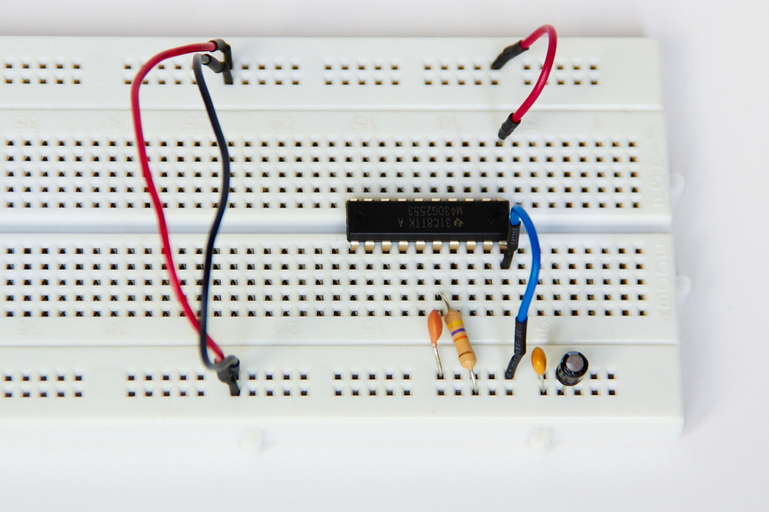
First-up we’ll build the basic MSP430G2553 on a breadboard. A few simple connections are needed: Step 1: MSP430 on a Breadboard
Connect What?
From Where?
To Where?
Jumper wires
Power & Ground rails on top
Power & Ground rails on bottom
10uF and 100nF capacitor
Power rail
Ground rail
Jumper wire
Power rail
Pin 1 (VCC) of MSP430G2553
Jumper wire
Ground rail
Pin 20 (GND) of MSP430G2553
47k Pull-up resistor
Power rail
Pin 16 (RST) of MSP430G2553
1nF capacitor
Ground rail
Pin 16 (RST) of MSP430G2553
We now have the basics of an MSP430 on a breadboard.
Connect the MSP-FET
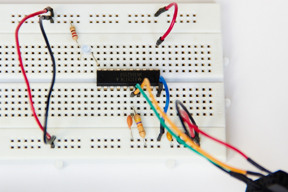
Now we’re ready to connect the MSP-FET to the breadboard. Step 2: Connect the MSP-FET to the Breadboard
The MSP-FET supports both JTAG and Spy-Bi-Wire connections – in choosing between these you’re basically trading off speed (JTAG) for fewer pins (SBW). As we’re working with a 20-pin microcontroller, I’ve chosen the Spy-Bi-Wire, happy to trade speed for fewer pins. I’ve also used the MSP-FET to power the project.
When connecting the pins on the FET, take note that the pinout diagram on the back of the FET is as you would look at it on a PCB – in other words it is a mirror of the pins on the end of the connector. If you’re not sure, use a Multimeter to test the GND and VCC_TOOL pins. Once you’re sure of the orientation:
Connect What?
To What?
Power rail
Pin 2 (VCC_TOOL) on the MSP-FET
Ground rail
Pin 9 (GND) on the MSP-FET
Pin 16 (SBWTDIO) on MSP430G2553
Pin 1 (TDO/TDI) on the MSP-FET
Pin 17 (SBWTCK) on MSP430G2553
Pin 7 (TCK) on the MSP-FET
Make the MSP430 go Blink
Now that we’re setup let’s get a sample project going to blink an LED. In the image in step 2 above you’ll see that I’ve connected an LED to pin 2.2 (along with the required resistor).
Create a new project in Code Composer Studio, and copy the below code into the main.c module. The code is quite straightforward, as I’ve avoided using Timers for the sake of simplicity (if you want to know more about timers, then check out this post).
#include <msp430.h>

/*
 * main.c
 */
int main(void) {
   WDTCTL = WDTPW | WDTHOLD;	// Stop watchdog timer

   P2DIR |= (1<<2);	//Set p2.2 as output;

   while (1)
   {

      volatile unsigned int i;

      //Set delay by counting
      i=0;
      do
      {i++;
      }
      while (i<20000);

      //Toggle pin P2.2
      P2OUT ^= (1<<2);

   }

   return 0;
}
Once you’ve entered the code, give it a quick compile to check that there are no errors.
Connect your FET and start debugging
Connecting your MSP-FET is really straightforward. Follow the instructions in TI’s hardware user guide to get connected (section 1.16/1.17).
The USB drivers are installed as part of Code Composer Studio (CCS), but may take a few minutes to recognise the hardware. When you upload code to your breadboard, CCS checks whether the firmware on the MSP-FET is up to date – if not, then you’ll be prompted to upgrade.
If you’ve used a LaunchPad before, then the FET works exactly the same. Click on the little bug icon (or hit F11), and away you go. If you’re new to using the CCS debugger, then I recommend taking a look at the CCS Wiki page.
Thanks
I hope that this has helped to get you kicked off with the MSP-FET. Drop me a line if you have any thoughts, comments, suggestions, projects…
A few years ago I discovered that my programming skills could be used to make real-world things move and flash and beep - I haven't looked back since! I love sharing what I've learned along this pretty bumpy (but very exciting) journey into the world of embedded systems - and that's why this website exists.
In addition to the website, I write a series for Nuts & Volts magazine that helps readers to move beyond the Arduino and into the world of AVR.
I'm a dad with a couple of energetic youngsters and a really cool wife!


Leave a Reply