
Troubleshooting an Embedded System

Busted by a Battery
How two Batteries taught me how NOT to troubleshoot a problem
I’m sure that you, along with most hobbyists, enthusiasts, and even embedded engineers, have had kick-yourself-afterwards moments. I did well recently, with two such moments in 7 days – over the past week, I’ve cursed, paced, pulled at my (thinning) hair, doubted myself, and wasted hours and hours.
I was doing final tests before shipping my first set of prototyped-and-tested Toadstool PCBs, when I encountered problems with two of the boards. In each case I ignored obvious signs in my approach to solving the issues, instead heading down a rabbit hole. Read on to find out where the wheels fell off, to check how you would have solved these problems, and to learn how NOT to troubleshoot a problem.
1. The Irregular Voltage Regulator
I was running a final test on a batch of Toadstool Mega328 boards before I shipped them. Nuts & Volts magazine had felt that they worked well with the series of articles I’m writing for them, and agreed to stock them in their online store. The boards needed to be shipped in time for the magazine print-run, so pressure was on.
I had been through two rounds of prototyping and extensive testing, so I was whistling as I packed the boards for shipping. Then the unthinkable happened as I uploaded sample code – I saw my Atmel ICE debugger was reporting 4V from the board, when it should have been running at 5V. How could that be, I’d done full testing on the first and second prototypes?
The Toadstool uses an adjustable voltage regulator which, when combined with appropriate resistors, allows the user to select a 3.3V or 5V operating voltage for the board. This LD1117 regulator from ST Micro was my starting-point into attempting to solve the problem – it contained the most complexity, and therefore the highest likelihood of causing the problem. Or so I thought.
Frustration
What followed was hours of validating my resistor calculations, checking the board layout, testing to ensure the resistors were within spec and placed on the board correctly, head-scratching, and even manually wiring up a hand-soldered LD1117 SOT package to check the outputs. What really confused me along the way was that the 3.3V output was spot-on, it was only the 5V that was coming in under.
The solution was very simple – it’s very likely that (as an objective observer) you can guess what the problem was. But before we reveal all, let’s take a look at the second issue.
2. The Case of the Real Time Clock

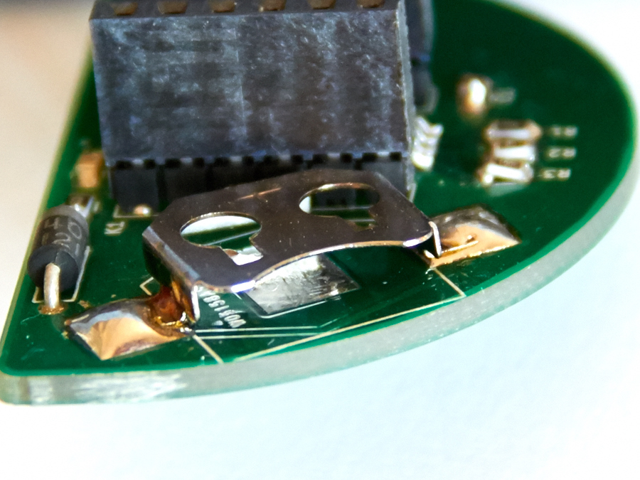
I had developed and tested a Real Time Clock module, designed for use with the Toadstool prototyping boards. These modules for the Toadstool boards are called “Caps”, and stack nicely on a common header to add functionality to projects. This Cap was an RTC based on Microchip’s MCP79400, and included a coin-cell holder and components to support the RTC’s battery backup functionality (when the main power fails, the RTC switches to a backup battery so it continues to keep time).
The last bit of functionality I needed to test was the backup battery. I was checking the time on the RTC over a serial connection to a PC, using a USB-Serial Cap I’m also working on. When I disconnected the power from the RTC, the time was retained – it seemed to work fine. That is, until I disconnected the USB-Serial Cap from the PC – when I reconnected power, the RTC had reset the time. I must add that I wasn’t powering the board from the USB-Serial converter, and only had RX/TX and GND connected.
Frustration – Again!
There were a number of possible reasons why the backup battery could have failed, but I focussed initially on the software as it was the most complex element. In order for the backup battery functionality to work, a bit needs to get set in one of the MCP79400 registers – so I spent an hour inserting debug statements to ensure the bit was being set and then not being un-set anywhere. From there I went on to the physical: trying to establish a pattern around the disconnection of the USB-Serial convertor, testing trace continuity on the board from the coin-cell holder to the MCP79400. I noticed that I wasn’t picking up a voltage on the RTC when running off backup battery, but when I tested the battery it read at 3.3V; and the traces from the coin-cell holder to the IC were ok.
After posting on a forum, asking for an alternate point of view, someone suggested that the current over the USB-UART RX line may leak enough to cause the RTC to retain the time. This meant that the backup functionality was never actually working. From here, I found the solution fairly easily.
The Solutions
Did you manage to identify the issues? Read on…
Voltage Regulator
The problem with the voltage regulator was completely external – the 9V battery that I was using to power my testing was effectively flat, only reporting 6V. If you feed this 6V into the board, take into account the voltage drop over the reverse-polarity protection diode and the voltage drop on the voltage regulator itself, the 6V will have dropped to 4V. This was exactly the reading I was getting, and also explained the reason why the regulator was correctly generating the 3.3V. A flat battery? It’s as bad as not having your PC plugged in to the power and wondering why it won’t turn on!
Real Time Clock
You would have thought I learned from the flat battery? Well, I did kind-of – I tested that the coin cell was charged. What I ignored, though, was the fact that there was no voltage present on the RTC when main power was disconnected – the traces were all fine. The issue here was a common one – connectivity. The pad for the negative-terminal of the coin-cell must have been microns lower than the PCB’s green solder mask layer – so when fully inserted, the coin cell’s negative terminal just wasn’t quite making contact with the pad on the PCB.
How (Not) to Troubleshoot a Problem
There are a number of formal and structured approaches to troubleshooting problems, across a variety of disciplines (software, hardware, embedded systems, even healthcare). Some are fairly cumbersome (more suited to more complex problems), and probably not useful here. Whether you choose to follow a formal methodology is, in my mind, not important for hobbyists and enthusiasts. What is important, though, is that you use a structured approach to solving the problem. This is where I fell short.
If I look at how I was attempting to troubleshoot my problems, I did a few things wrong.
Don’t jump right in
Instead of approaching the problem in a structured way, I simply assumed that the most complex system caused the problem. In the words of Jack Ganssle in one of his articles, “think, don’t do”. I should have noted down a series of items that I planned to troubleshoot – this would have forced me to think about a wider range of possible causes.
The Easy Stuff First
I started out with the most complex things. If I had made a list of items to test, I could have then tackled the easy items first. Another online article highlights this in their guide to troubleshooting.
Make Notes
My troubleshooting took a few days as I didn’t have a block of time to dedicate to solving the issues. If I had made notes about what I tested and the outcomes, it would have helped me to pick up where I left off. Notes would also have reminded me of what did work and help me to narrow down the problem and identify other possible tests to perform.
Methodical and Thorough
The lack of structure in my approach meant that I wasn’t being thorough or methodical. For example, if I had tackled things more thoroughly with the voltage regulator, one of the paths I would have followed would have been from the regulator back to the source – in this instance I would have picked up the problem with the battery.
Over to You!
How have you approached troubleshooting in the past? Please share your insights (and horror stories!), so that others can learn from your experiences.

I’ve just completed my brand new guide Arduino to AVR: Get Started in 3 Steps.
Get it now on Payhip for only $1.65.
Challenge yourself and learn how to gain the flexibility and additional control that the AVR microcontroller offers.
As a free bonus, get an ATmega328P pinout cheatsheet.
A few years ago I discovered that my programming skills could be used to make real-world things move and flash and beep - I haven't looked back since! I love sharing what I've learned along this pretty bumpy (but very exciting) journey into the world of embedded systems - and that's why this website exists. In addition to the website, I write a series for Nuts & Volts magazine that helps readers to move beyond the Arduino and into the world of AVR. I'm a dad with a couple of energetic youngsters and a really cool wife!
Rule 1 it’s always the power supply. Rule 2 Even when you’ve checked the power supply, it’s always the power supply.
Absolutely!
Back in the day I used to make prototypes for peripheral interfaces for mini computers using wire wrapping techniques. These were big circuits of maybe 50 TTL ICS. To check my wiring I often used a DVM but back then you had to read the DVM display as there was no buzzer which made progress very slow. So I decided to lash up a simple buzzer to check continuity. It was 2 AA cells, a little buzzer and some test probes. I didn’t have a battery holder so I soldered on the wires. Now to my great surprise it didn’t work. Each battery checked OK but nothing measured for the pair! Eventually it turned out that the soldering heat damaged the batteries. Only when pressed by the meter probes did the terminals connect internally and show a voltage. This didn’t do my street cred much good. What were the chances that the prototype design would work if I couldn’t even make a buzzer work?…
Thanks for sharing, I had a chuckle! An tough one to pick up that the batteries had been damaged.
Cheers
Andrew